Milestone
Downloads
- Video (YouTube mirror: Mirror)
- Presentation Slides
Progress Summary
Our project consists of two components. The first component is the raymarcher, which is the main tool that we will use for rendering scenes. The second component is more interesting. Here, our goal is to add detail to surfaces via distance field “textures”. Namely, each object in the scene is given a distance field that locally describes high quality surface details. We can then use our raymarcher to render the entire scene efficiently.
So far, we have a complete working implementation of a raymarcher, and we have some preliminary results for our distance field texture methods. Our raymarcher can render any distance field, and does some very basic shading. Our distance field texture methods are more involved; we currently have three ideas implemented.
Preliminary Results
The Raymarcher:
Below is an image of the Menger Sponge fractal (the 3D analogue of the Sierpinski carpet). The image was rendered entirely using a distance field and our raymarcher, i.e. there is no triangle mesh. This image demonstrates the basic functionality of our raymarcher.
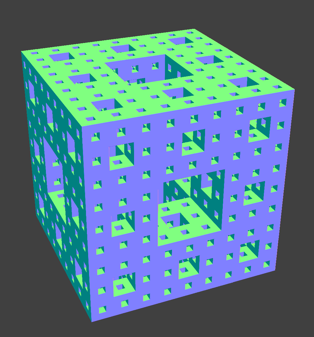 Menger sponge Menger sponge |
Fractal Microgeometry:
Idea 1: We represent each triangle in the scene (that will have microgeometry) as a distance field. When a ray gets within distance delta of a particular triangle, we enter “shell space” for that triangle and use the distance field texture to perturb the distance to the triangle. Specifically, we convert the ray to local shell coordinates, and then we compute its distance to the triangle using the distance given by the distance field texture at the local coordinates. We then take the max of this distance and the distance to the basic triangle + delta to ensure that the distance field texture does not stray beyond the delta-radius shell about the triangle.
The images below demonstrate this idea for a tetrahedron.
 Distance field texture Distance field texture |
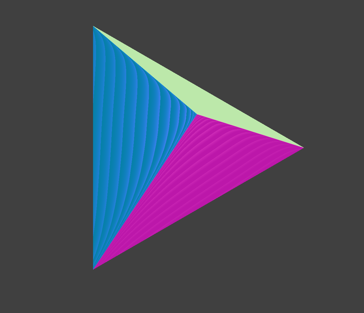 Basic tetrahedron Basic tetrahedron |
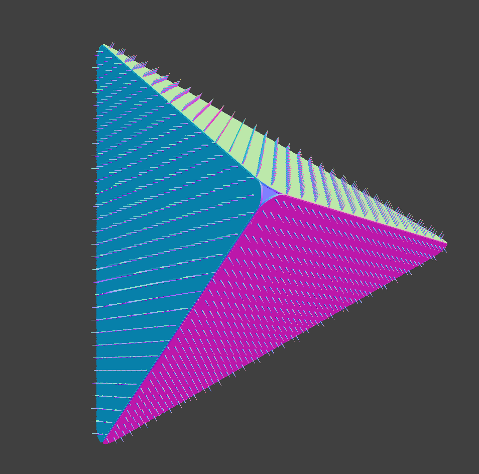 Tetrahedron with distance field texture Tetrahedron with distance field texture |
Issues: The main problem is that the base of the shells can overlap. This can cause the local distance field textures overlap in world space, creating clipping artifacts. One way to fix this is to shrink each triangle slightly so that the shells do not overlap (this was done in the image above) However, this causes the corners of the triangles to now be rounded and not touching.
Idea 2: We represent the base geometry as a 3D distance field, and encode the distance field textures as a 4D distance field. The inputs to the 4D distance field are (x,y,z,h): (x,y,z) is the position in world space, and h is the distance given by the 3D distance field at (x,y,z). The 4D distance field gives us the distance to the nearest surface in the scene given the (x,y,z) position of the ray and h, which is the distance of the ray to the basic geometry. Below is a scene demonstrating this idea. The base 3D distance field is a simple torus, and the 4D distance field embeds small details onto it.
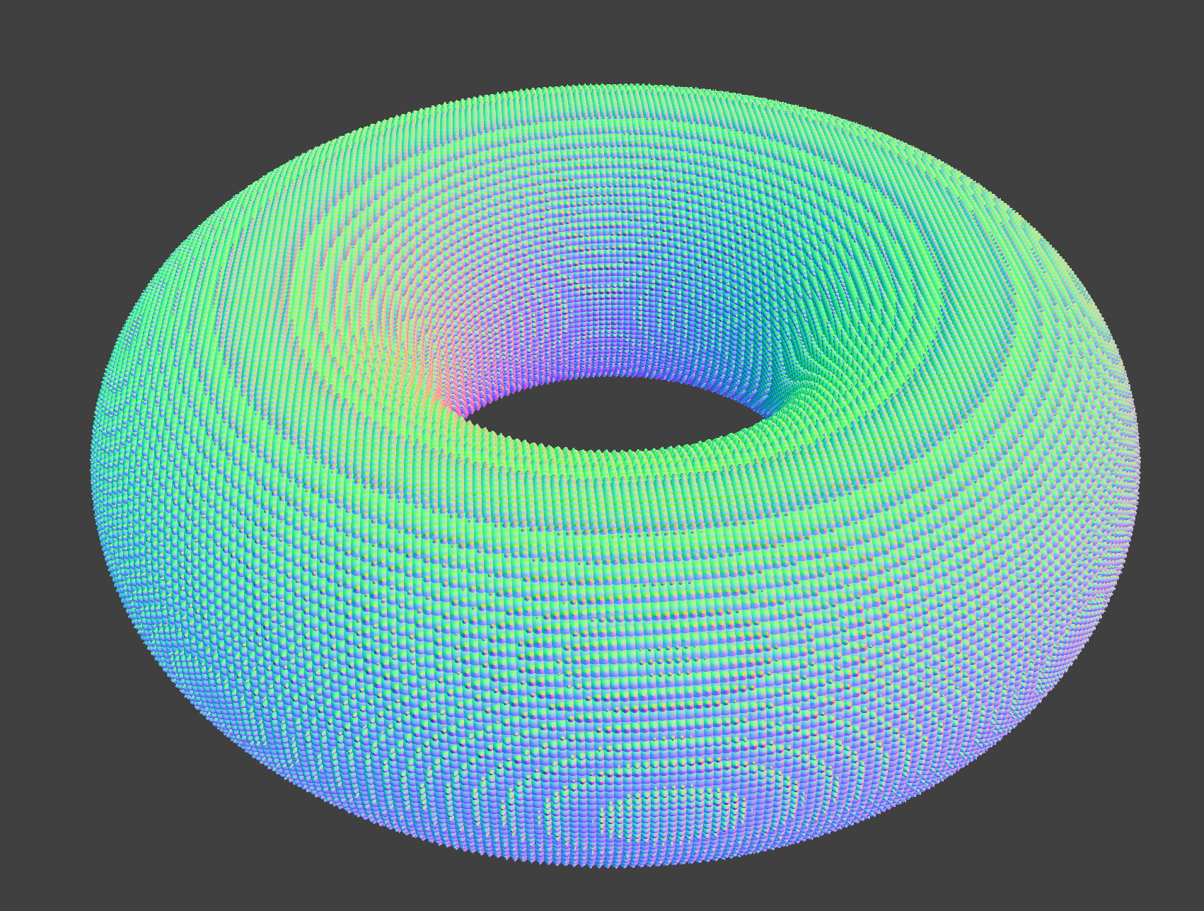 Torus with detail Torus with detail |
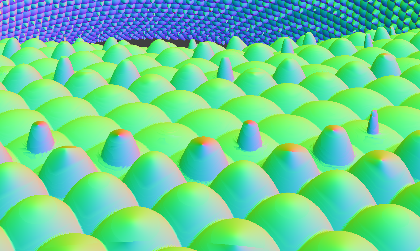 Closeup of added detail Closeup of added detail |
Issues: The main problem here is that it is unclear how to encode the 3D basic geometry + distance field textures as a 4D distance field.
Idea 3: This idea is similar to idea 1, only we use the default rasterization vertex shader to find the first delta-radius shell that the ray intersects. Then, we proceed as before using the raymarcher. Now, the local coordinates are determined as (u,v,h), where (u,v) are texture coordinates and h is the distance to the base geometry.
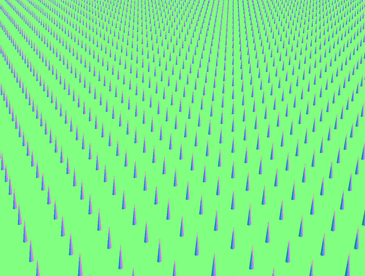
Below are two scenes demonstrating this technique. We put the spike field first onto a cube, and then onto a teapot.
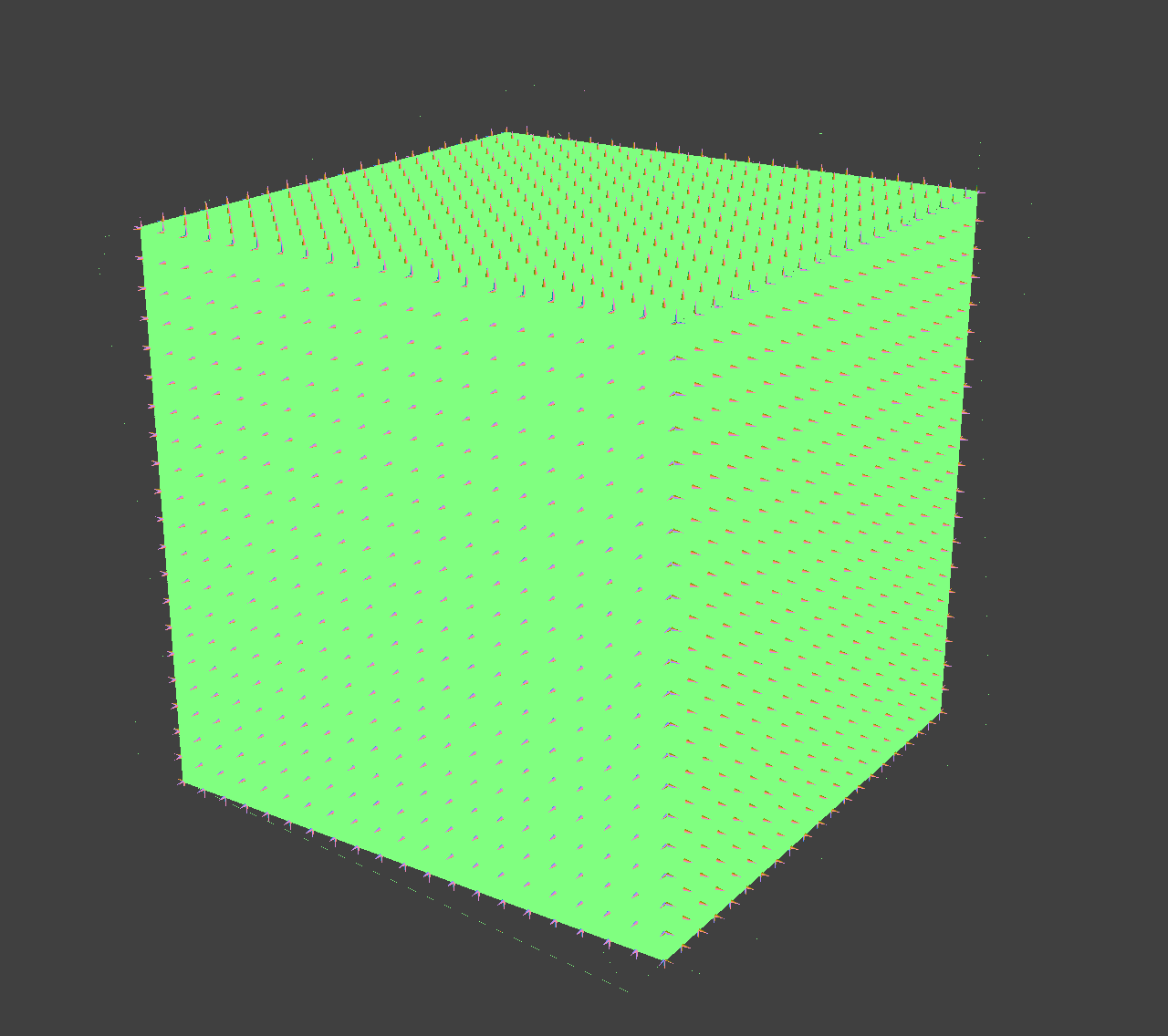 Spike cube Spike cube |
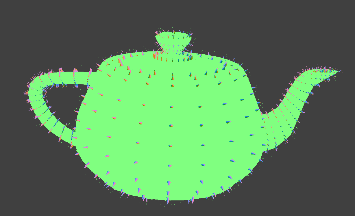 Spike teapot Spike teapot |
This technique poses an interesting additional challenge that does not appear in idea 1. In idea 1, to prevent the distance field texture from being rendered outside of the shell, we simply intersect the local distance field texture with the triangle’s shell that contains the texture. However, this no longer works for idea 3, since the shell is no longer represented as a distance field. Instead, we do one raytrace to compute t_exit of the ray for the shell that it hit, and then do raymarching, requiring that t < t_exit. Our computation of the exit point is currently a bit buggy, which is why there is some noise in the above two images, more noticeably on the teapot.
The images below illustrate the artifacts we get when we do not do this additional step. Notice how the top of the plane looks funny. This is because at the top of the plane, a ray passed through the shell and hit the plane in the distance field texture, which is beyond the triangle-mesh plane’s surface.
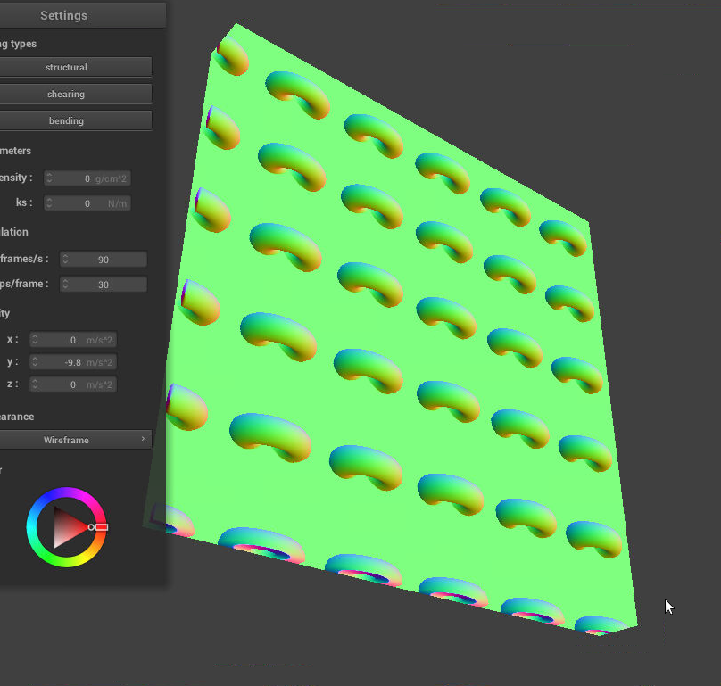 Artifact: plane extends beyond original mesh Artifact: plane extends beyond original mesh |
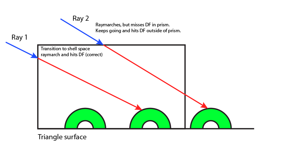 Why the artifact occurs Why the artifact occurs |
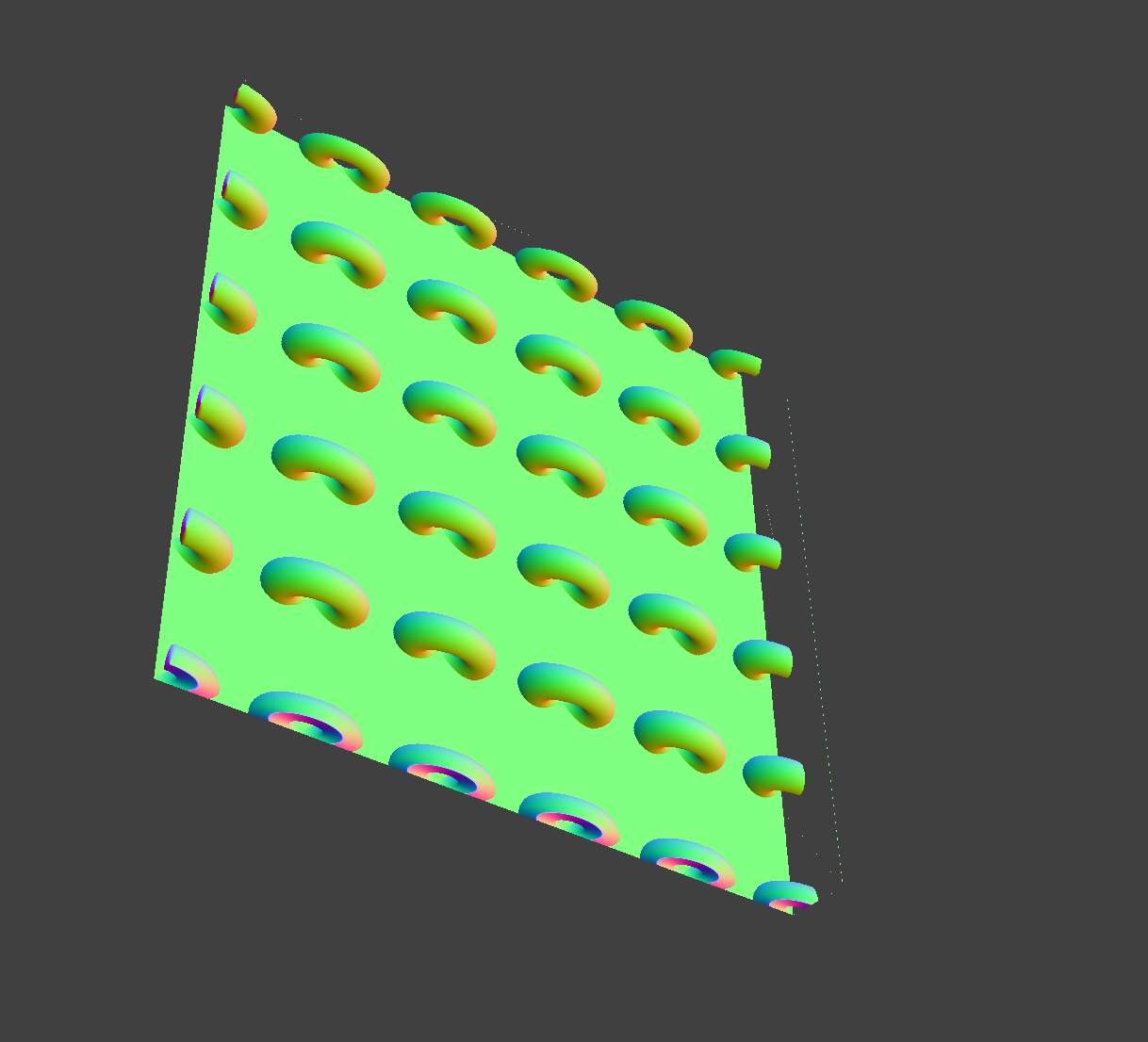 Artifact mostly fixed with raytrace Artifact mostly fixed with raytrace |
Fractal Design:
We have also been working on using iterated function systems (IFS) to define plant-like fractals. A method for generating these fractals, chaos game algorithms, works roughly as follows. We first define an initial set to start the fractal, then iteratively apply the set of transformations (randomly) and finally take the union of the transformed sets to get the fractal. Currently, we have implemented the chaos game algorithm outlined here. We have used the algorithm to generate the elm tree fractal using Hart’s transformations found here. The fractal we constructed is shown below, and was rendered using an IFS builder found online.
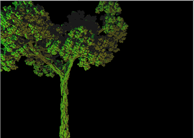 Fractal tree Fractal tree |
Progress Relative to Plan
Our project is very much on schedule. Idea 3 works very nicely for the fractal microgeometry and is very efficient (easily realtime). There remain two things for us to do. First, we need to fix the buggy raytrace step to remove the noise in the cube/teapot images. Then, we need to put together a complete scene demonstrating the advantages of our microgeometry rendering technique. The scene should be properly shaded and visually appealing. We will most likely use our technique to render dense foliage in the scene.
Updated Work Plan
No updates necessary; we are on schedule!